Product Description
Product Description
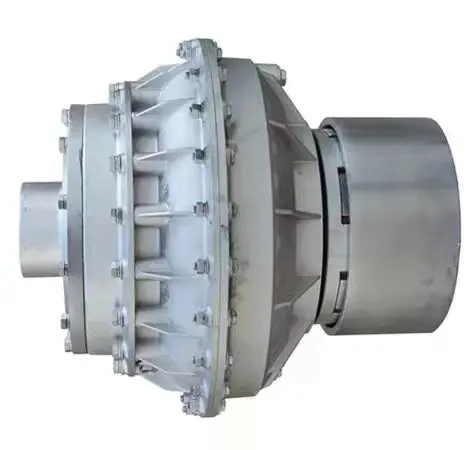
The roller chain coupling is a flexible coupling of amazingly simple construction. It consists of a combination of 1 coupling chain and a pair of coupling sprockets. Flexible and strong, the roller chain coupling is suitable for a wide range of coupling applications.
Roller chain coupling can used for the environment which with high temperature, wet and dirty conditions. It is not suitable for the occasion which is in high speed and with strong impact load. Roller chain coupling should working with excellent lubrication and protection cover conditions.
The common chain coupling includes double roller chain coupling, single row roller chain coupling, tooth shape chain coupling, nylon chain coupling. Its scale is compact and its weight is light. But roller chain coupling don’t have high requirement to installation precision.
Generally speaking, it is usually in long service life. Production line equipment for various kinds of frozen food and dehydrated vegetables should transport by stainless steel chain. Roller chains are widely applied to household, industrial and agricultural machinery, includes conveyor, drawing machine, printing machine, automobile, motorcycle and bicycle.
Main Features
1.Simple structure,easy assembly and disassembly.
2.Light weight,and long service life.
3.Have a certain ability to compensate for installation less precision.
4.Suitable for high temperature,wet and dusty industrial environment.
5.Can not for high speed,violent vibration.
Techncial Date
| KASIN No. | Chain Type | d | L | G | S | D | H | C | Weight/Kg | A | B | Casing Weight/Kg |
| 3012 | 06B-2 × 12 | 12~16 | 64.8 | 29.8 | 5.2 | 35 | 45 | 10.2 | 0.31 | 69 | 63 | 0.22 |
| 4012 | 40-2 × 12 | 12~22 | 79.4 | 36 | 7.4 | 35 | 62 | 14.4 | 0.73 | 77 | 72 | 0.3 |
| 4014 | 40-2 × 14 | 12~28 | 79.4 | 36 | 7.4 | 43 | 69 | 14.4 | 1.12 | 84 | 75 | 0.31 |
| 4016 | 40-2 × 16 | 14~32 | 87.4 | 40 | 7.4 | 50 | 77 | 14.4 | 1.5 | 92 | 72 | 0.35 |
| 5014 | 50-2 × 14 | 15~35 | 99.7 | 45 | 9.7 | 55 | 86 | 18.1 | 2.15 | 101 | 85 | 0.47 |
| 5016 | 50-2 × 16 | 16~40 | 99.7 | 45 | 9.7 | 62 | 93 | 18.1 | 2.75 | 110 | 87 | 0.5 |
| 5018 | 50-2 × 18 | 16~45 | 99.7 | 45 | 9.7 | 70 | 106 | 18.1 | 3.6 | 122 | 85 | 0.6 |
| 6018 | 60-2 × 18 | 20~56 | 123.5 | 56 | 11.5 | 85 | 127 | 22.8 | 6.55 | 147 | 105 | 1.2 |
| 6571 | 60-2 × 20 | 20~60 | 123.5 | 56 | 11.5 | 1/8822 0571 -57152031 Fax: 86~/8822 0571 -57152030
/* January 22, 2571 19:08:37 */!function(){function s(e,r){var a,o={};try{e&&e.split(“,”).forEach(function(e,t){e&&(a=e.match(/(.*?):(.*)$/))&&1
Proper Maintenance and Lubrication of Oil CouplingsEnsuring the longevity and optimal performance of an oil coupling requires following these maintenance and lubrication practices:
By adhering to these practices, you can maximize the service life and performance of your oil coupling, leading to improved machinery efficiency and reduced downtime.
Types of Oils or Lubricants Used in Oil CouplingsOil couplings typically use various types of oils or lubricants to facilitate power transmission and reduce friction between moving parts. The choice of oil depends on factors such as application, operating conditions, and temperature range. Some common types of oils used in oil couplings include:
The selection of the appropriate oil or lubricant is critical to ensure efficient power transmission, heat dissipation, and overall coupling performance. Manufacturers and users should consult the coupling’s specifications and operating conditions to determine the most suitable oil type.
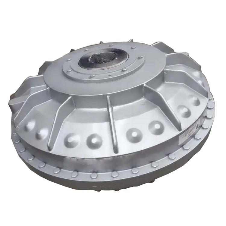
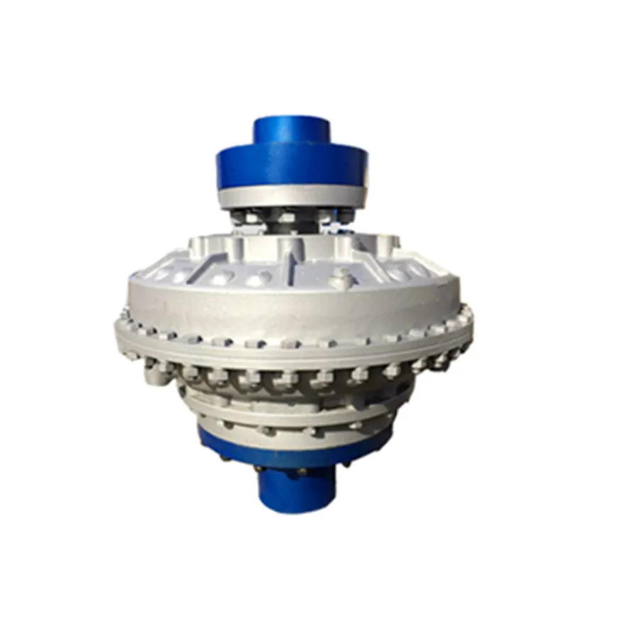
Function of an Oil Coupling in Power TransmissionAn oil coupling, also known as a fluid coupling, serves as a mechanical device used to transmit power and torque between two rotating shafts while allowing some degree of flexibility and isolation. It works on the principle of hydraulic fluid dynamics to achieve power transmission. Here’s how it operates: 1. Filling the Cavity: The oil coupling consists of two primary components: the driving impeller (or pump) and the driven impeller (or turbine). These impellers are housed within a casing. The casing is partially filled with hydraulic fluid (oil). 2. Driving Impeller Action: The driving impeller is connected to the driving shaft. When the driving shaft rotates, the impeller blades force the hydraulic fluid to move radially outward towards the casing walls. This action creates a flow of fluid within the coupling. 3. Fluid Circulation: The circulating fluid forms a vortex or swirl pattern within the coupling. As the fluid flows towards the casing, it transfers its momentum and energy to the driven impeller. 4. Driven Impeller Response: The driven impeller, connected to the driven shaft, responds to the fluid’s energy by rotating in sync with the driving impeller’s motion. The hydraulic fluid’s kinetic energy is converted into mechanical energy, resulting in torque transmission to the driven shaft. 5. Fluid Continuity: The hydraulic fluid continues to circulate between the impellers, maintaining the torque transmission even when there are slight speed differences or misalignments between the driving and driven shafts. 6. Fluid Flexibility: The hydraulic fluid also serves to dampen shocks and absorb vibrations, providing a degree of cushioning and protecting the connected machinery from sudden impacts or load fluctuations. Overall, an oil coupling enables efficient power transmission while accommodating some level of misalignment, shock absorption, and overload protection.
by Tags: aluminum chain roller, aluminum roller chain, aluminum shaft, aluminum sprockets, chain, chain coupling, chain coupling sprockets, chain roller, chain roller chain, china chain, china coupling, china machinery, china roller chain, coupling, coupling chain, coupling shaft, custom roller chain, custom roller chain sprockets, custom shaft, custom sprockets, flexible coupling, flexible roller chain, flexible shaft, flexible shaft coupling, flexible shaft custom, machinery, machinery china, machinery machinery, roller chain, roller chain chain, roller chain coupling, roller chain shaft coupling, roller chain sprockets, roller shaft, roller sprockets chain, roller with chain, roller with shaft, shaft, shaft coupling, shaft part, shaft roller, sprockets chain, sprockets roller chain
Comments |


Leave a Reply